Description
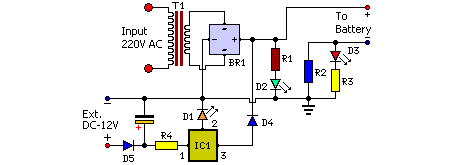
Mobile phone chargers available in the market are quite expensive. The circuit presented here comes as a low-cost alternative to charge mobile telephones/battery packs with a rating of 7.2 volts, such as Nokia 6110/6150.Circuit diagram:
Parts
- R1 = 1K
- R2 = 47R
- R3 = 10R
- R4 = 47R
- C1 = 1000uF-25V
- D1 = LEDs any color
- D2 = LEDs any color
- D3 = LEDs any color
- D4 = 1N4007
- D5 = 1N4007
- IC1 = LM7806
- T1 = 9VAC Xformer 250mA
- BR1 = Diode bridge 1A
Circuit Operation:
The 220-240V AC mains supply is down-converted to 9V AC by transformer T1. The transformer output is rectified by BR1 and the positive DC supply is directly connected to the charger’s output contact, while the negative terminal is connected through current limiting resistor R2. D2 works as a power indicator with R1 serving as the current limiter and D3 indicates the charging status. During the charging period, about 3 volts drop occurs across R2, which turns on D3 through R3.An external DC supply source (for instance, from a vehicle battery) can also be used to energies the charger, where R4, after polarity protection diode D5, limits the input current to a safe value. The 3-terminal positive voltage regulator LM7806 (IC1) provides a constant voltage output of 7.8V DC since D1 connected between the common terminal (pin 2) and ground rail of IC1 raises the output voltage to 7.8V DC. D1 also serves as a power indicator for the external DC supply. After constructing the circuit on a veroboard, enclose it in a suitable cabinet. A small heat sink is recommended for IC1.
Description
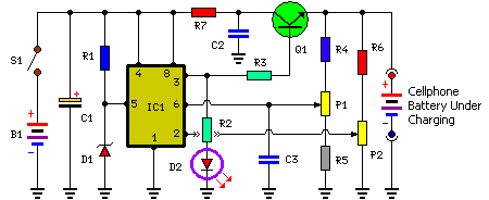
Charging of the mobile phone, cellphone battery is a big problem while traveling as power supply source is not generally accessible. If you keep your cellphone switched on continuously, its battery will go flat within five to six hours, making the cellphone useless.A fully charged battery becomes necessary especially when your distance from the nearest relay station increases. Here’s a simple charger that replenishes the cellphone battery within two to three hours. Basically, the charger is a current-limited voltage source. Generally, cellphone battery packs require 3.6-6V DC and 180-200mA current for charging. These usually contain three NiCd cells, each having 1.2V rating.
Current of 100mA is sufficient for charging the cellphone battery at a slow rate. A 12V battery containing eight pen cells gives sufficient current (1.8A) to charge the battery connected across the output terminals. The circuit also monitors the voltage level of the battery. It automatically cuts off the charging process when its output terminal voltage increases above the predetermined voltage level.
Circuit diagram:
Parts:
- P1 = 20K
- P2 = 20K
- R1 = 390R
- R2 = 680R
- R3 = 39R-1W
- R4 = 27K
- R5 = 47K
- R6 = 3.3K
- R7 = 100R-1W
- C1 = 4.7uF-25V
- C2 = 0.01uF
- C3 = 0.001uF
- D1 = 5.6V-1W Zener
- D2 = 3mm. Red LED
- Q1 = SL100
- S1 = On/Off Switch
- B1 = 1.5vx8 AA Cells in Series
- IC1 = NE555 Timer IC
Circuit Operation:
Timer IC NE555 is used to charge and monitor the voltage level in the battery. Control voltage pin 5 of IC1 is provided with a reference voltage of 5.6V by zener diode D1. Threshold pin 6 is supplied with a voltage set by P1 and trigger pin 2 is supplied with a voltage set by P2. When the discharged cellphone battery is connected to the circuit, the voltage given to trigger pin 2 of IC1 is below 1/3Vcc and hence the flip-flop in the IC is switched on to take output pin 3 high. When the battery is fully charged, the output terminal voltage increases the voltage at pin 2 of IC1 above the trigger point threshold.This switches off the flip-flop and the output goes low to terminate the charging process. Threshold pin 6 of IC1 is referenced at 2/3Vcc set by P1. Transistor Q1 is used to enhance the charging current. Value of R3 is critical in providing the required current for charging. With the given value of 39-ohm the charging current is around 180 mA. The circuit can be constructed on a small general-purpose PCB.
For calibration of cut-off voltage level, use a variable DC power source. Connect the output terminals of the circuit to the variable power supply set at 7V. Adjust P1 in the middle position and slowly adjust P2 until LED (D2) goes off, indicating low output. LED should turn on when the voltage of the variable power supply reduces below 5V. Enclose the circuit in a small plastic case and use suitable connector for connecting to the cellphone battery.


No comments:
Post a Comment